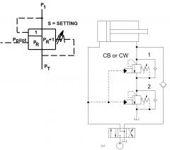

The circuit shows two counterbalance valves in series to increase the load-holding pressure yet allow for a lower pilot pressure to control load.
- Standard counterbalance valve : CB**
- Vented counterbalance valve : CW**
Benefits of this circuit arrangement:
- The pressure in the return line of counterbalance valves is additive to the setting with a factor of the pilot ratio plus one. The back pressure can be used to intentionally boost the setting of a counterbalance valve.
- In the example, CBV 1 has a setting of 3000 psi and a pilot ratio of 3:1 CBV 2 has a setting of 500 psi and pilot ratio 10:1
- CBV 1 won't open unless inlet pressure exceeds 5000 psi. (3000 + (3+1)x 500 = 5000 psi)
- With increasing pilot pressure, CBV 2 will start to open (at 45 psi) before CBV 1 starts to open (depending on load-induced pressure, cylinder ratio). Once CBV 2 is essentially out of the way, the setting of CBV 1 will be returned to its original setting for normal operation.
- In order for this work as designed, back pressure downstream of CBV 2 must be zero.
Note: Having two counterbalance valves in series back pressure creates a multiplication effect that boosts the setting (with factor: (pilot ratio plus 1) squared)
CBV 1 can be a standard valve CB** or a vented CW** with port 4 connected to port 2.
For Sun technical support, contact Bernhard Kristen.