外接口开启, 弹簧偏置关闭, 非平衡锥阀 逻辑单元 带口1导压 和 集成T-8A控制插孔


此阀为非平衡,外控开启,2通逻辑开关单元且带集成先导级控制插孔。此阀在弹簧偏置下处于关闭状态且用口1作为先导源。当安装在T-8A插孔中的先导级2通阀处于关闭状态,逻辑单元会保持关闭状态。当先导级2通阀开启,只要有足够的组合压力(口1与口2)克服弹簧力,逻辑阀将开启。口3产生的作用力加上弹簧力必须比口1和口2产生的作用力之和大,阀才能保持关闭状态。注意:先导面积(口3)是口1作用面积的1.8倍且为口2作用面积的2.25倍。
- 此类阀在口2与先导口之间有着有效密封。
- 注意:带T-8A控制选项,应首先用正确的扭矩安装主级阀。然后用合适的扭矩将T-8A先导级控制阀安装进主级阀中。
- T-8A控制类型允许通过T-8A插孔将先导级控制阀直接旋进逻辑阀的顶部。这些先导级控制阀需单独采购并包括电比例,电磁,气控先导,液控先导操作。请参照先导级控制阀。
- 当外接口导通时,此类阀将迅速打开。但是关闭时间很难预测,因为这取决于流量和相应产生的压降。
- 因为此类阀为非平衡,所以切换取决于压力。锥阀芯的打开和关闭是三个区域的力平衡结果:口1区域=100%,口2区域=80%,和先导口区域=180%
- 此类阀会受所有端口压力影响,因此应考虑一个完整周期内系统各方面的操作情况。任何一个端口压力变化都可能会导致阀从关闭切换到打开位置,反之亦然。一个完整油路中所有可能的压力变化都需要被考虑,以此确保设计的系统安全、可靠。
- 所有端口都可以接受5000 psi (350 bar)的压力。
- 利用Sun浮动结构减少由于过量安装扭矩或插孔/插装阀加工误差带来的内部零件粘结的可能性。
| 插孔 | T-2A |
| 系列 | 2 |
| 通流能力 | 50 gpm200 L/min. |
| 最大操作压力 | 5000 psi350 bar |
| .07 in³1,1 cc | |
| A3与A1的面积比 | 1.8:11.8:1 |
| A3与A2的面积比 | 2.25:12.25:1 |
| 先导控制孔型 | T-8AT-8A |
| 控制阻尼孔直径 | .021 in.0,53 mm |
| 阀头部安装六角尺寸 | 1 1/8 in.28,6 mm |
| 阀安装扭矩 | 45 - 50 lbf ft61 - 68 Nm |
| Seal kit - Cartridge | Buna: 990202007 |
| Seal kit - Cartridge | Polyurethane: 990002002 |
| Seal kit - Cartridge | Viton: 990202006 |
Direct acting valves are used to prevent over pressure and pilot operated valves are used to regulate pressure. If you are unsure, use a direct acting valve. Sun's direct acting valves are very fast, dirt tolerant, stable, and robust. Sun's pilot operated valves are moderately fast, they have a low pressure rise vs. flow curve, and they are easy to adjust.
Because of the very high ratio, the COFO has limited capacity. The discharge path is across a .050 inch (1,3 mm) diameter orifice. If you have large accumulators combined with low precharge pressures, this may not discharge the energy quickly enough. Using the COFO XDN cartridge in conjunction with an LODA XDN will provide capacity for larger applications.
There are exactly 250 Sun drops in a cubic inch or 15 in a cc.
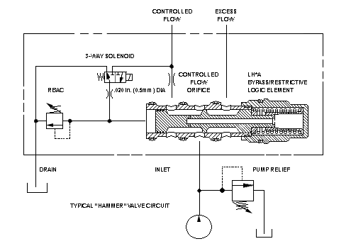
The LH*A family of valves has been optimized to be used in a package to provide a power source for hydraulic tools. We can quantify the performance of the valve in static conditions but we cannot tell you how it will do in your application.
For instance: You want to use the valve as a compensator for a load-sense power steering package. When you are steering the machine and raising an implement, the valve is in a bypass mode (throttling on the bypass side). When the implement actuator bottoms out, pressure jumps to maximum and now the valve needs to change to the restrictive mode. Since the LH*A is balanced against pressure on the bypass side the only thing moving the spool is its own spring. The time this takes is dependent on where the spool was to begin with and where it has to go.
During this transition the steering will see the pressure differential across it suddenly change from about 150 psi (10 bar) to a system pressure of say 3000 psi (200 bar) and suddenly back down to about 150 psi (10 bar). When this scenario was described to me it was termed the broken thumb syndrome.
Sun does not and cannot provide technical support for this type of application. The valve has been successfully used in similar applications. What is necessary to make it work is up to whoever is doing the application.
The valve was developed originally to power demolition hammers. The hammers are aftermarket accessories that are mounted on a large variety of excavators. The "hammer" circuit provides a method of tapping into the existing hydraulic system of the excavator, turning the tool on and off, controlling flow, and limiting pressure.
Every manufacturer of hammers has very specific needs as far as flow and pressure and there is a large disparity of hydraulic systems in the excavators. For this reason, Sun has never had a catalog package for this circuit.
Sun does not and cannot provide technical support for "hammer valve" installations.
- 组合插装阀(先导级和主级)集成块的信息仅供参考。插装阀必须单独订购并在使用时进行装配。
- Logic Element Cartridges Technical Tips
- 插孔节省™复合功能阀 简化你的液压方案
- Series 4 PLUS Cartridges Offer Higher Flows with Lower Pressure Losses
- Another Optimized Solution from Sun Hydraulics!
- More Options for Logic Elements with Position Indicating Switch
- T: 让您的系统更加灵活,让您的未来更加可期!
- Sun Cartridges with EPDM Seals
- QuickDesign with SmartConnect Offers Drag-and-Drop Schematic Tool
- Take the Guesswork Out of Logic Circuits.
- 减小泄压 冲击 &购置成本
- Pilot Controlled Directional Cartridges Technical Tips
- Sun推出抗腐蚀产品解决方案
- Sun FLeX™系列电磁阀&线圈
- Sun Introduces Additional Solenoid-Operated Pilot Valves
- Sun’s Cartridge Symbol Library


