
In this example, circuits demonstrate normally closed balanced elements upstream from a motor. When the cylinder pressure is satisfied, the valve will shift and allow oil to the motor.
- Sequence valve: RS*C
- Normally closed, balanced logic element: DK*P
- 3-way, direct-acting, directional valve: DRBC
- Normally closed, balanced logic element: MW*M
Benefits of this circuit arrangement:
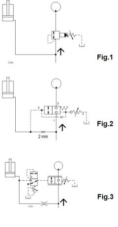
- Fig. 1 shows a sequence valve to ensure pressure on the (clamping) cylinder before the motor rotates (a drill).
- Fig. 2 The logic element DK is an adjustable, leak-free valve that doesn‘t open until pressure in a (long) hose builds up to clamp a (drilling) tool - e.g. with a cylinder. There is no minimum pressure drop required for flow to the motor once the logic valve is open.
- Fig. 3 shows a vented load control valve instead of the logic valve in circuit 2. It incorporates a reverse free-flow check. The 2/3-way DRBC unloads the pilot port of the MW*M to tank until P3 exceeds the setting of the DRBC.