
The circuits show three examples for redundancy in load-holding applications with counterbalance valves using balanced logic valves.
- Load-sensitive counterbalance: CB**
- Balanced logic element: DK*S
- Load-insensitive counterbalance : MB*M, MW*M
- Logic element with position indicator: LO*C-Z**
Benefits of this circuit arrangement:
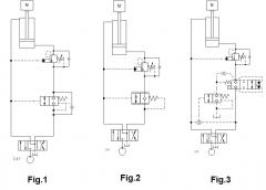
- Fig.1 shows a CBV with a balanced logic valve in the return line. The DK*S opens at 200 psi regardless of trapped pressure between counterbalance and DK*S. An additional reverse free flow check is required for lifting the load.
- Fig.2 shows a CBV valve with a balanced load control valve MB*M that incorporates the reverse free-flow check.
- Fig.3 shows a CBV with an unbalanced logic valve LO*C-Z** with position indication for safety indication. The LO*C is pilot operated via a balanced logic element ( DK*S ) which in turn is also piloted via a shuttle valve CS** for flow in both directions.
For Sun technical support, contact Steve Weber.