
The circuit shows counterbalance valves that open slower.
- Load-sensitive counterbalance: CB**, CE**, CW** , CA**
- Anti-shock relief : RP*T, RV*T
Benefits of this circuit arrangement:
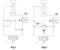
- Fig. 1 shows a combination of orifices to reduce the effective setting of pilot pressure (splitter orifice). It also delays the opening of the counterbalance valve. Both help to further dampen the circuit but requires setup time and fine tuning on the machine and does cause leakage.
- Fig. 2 uses an anti-shock relief valve to ramp up the pressure that moves the cylinder. It also ensures a smooth opening of the counterbalance valve.
CAUTION NOTE small orifices in the pilot line can trap pressure and keep the load-holding valve in an open position. Reverse free flow check valves are recommended so the loadholding valve can close quickly.
For Sun technical support, contact Steve Weber.