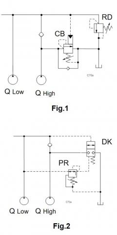

The circuits shows one pump for high pressure/low flow and another pump for high flow/low pressure driven by the same electric motor and feeding the same user. Both circuits unload pumps without decompression shock in the system.
- Standard counterbalance valve: CB**, CB*J
- Pressure relief valves: RD*A
- Balanced logic valves: DK*S
- Pressure-reducing valves: PR*R
- Y Assemblies: YRES (Series 2) , YRGJ (Series 3), YRIA (Series 4)
Benefits of this circuit arrangement:
- Fig.1 shows a CB unload the high-flow pump at a preset high pressure.
- Fig.2 shows a balanced logic valve unload the high-flow pump at a preset high pressure.
- The circuit allows the use of one motor with limited power to drive a double pump for either high flow or high pressure. When the system pressure rises, the high-flow pump is unloaded to tank to limit the power requirement from the electric motor.
For Sun technical support, contact Bernhard Kristen.